The Nissan Club banner

HOWTO - Manual to Automatic Digital Climate Control Conversion

179K views 52 replies 25 participants last post by  jserrano 
#1 · (Edited)
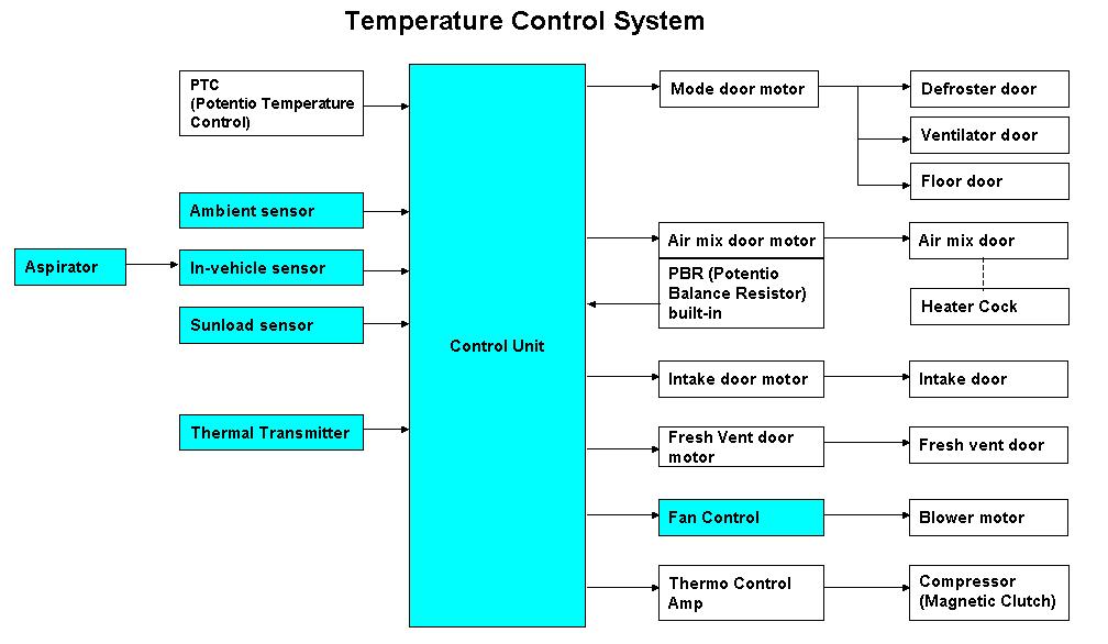
Back around late 2004, I had successfully completed a Heads-Up Display (HUD) project on my ’94 Altima SE which other members of this forum had already proven was very feasible. That project was very rewarding to me and it left a nice imprint in my psyche. Back then, I also envisioned that someday another project of that scale – an Automatic Digital Climate Control system – might also be within my capabilities and someday a reality. (http://www.nissanclub.com/forums/showpost.php?p=2270842&postcount=14)

I’ve made numerous remarks hinting and doing absolutely nothing in regards about it.

(http://www.nissanclub.com/forums/showpost.php?p=2295873&postcount=4)
(http://www.nissanclub.com/forums/showpost.php?p=2330557&postcount=11)

Well the time has come where I will either eat my words or otherwise prove that with determination and commitment many things are possible, however remote they may seem.

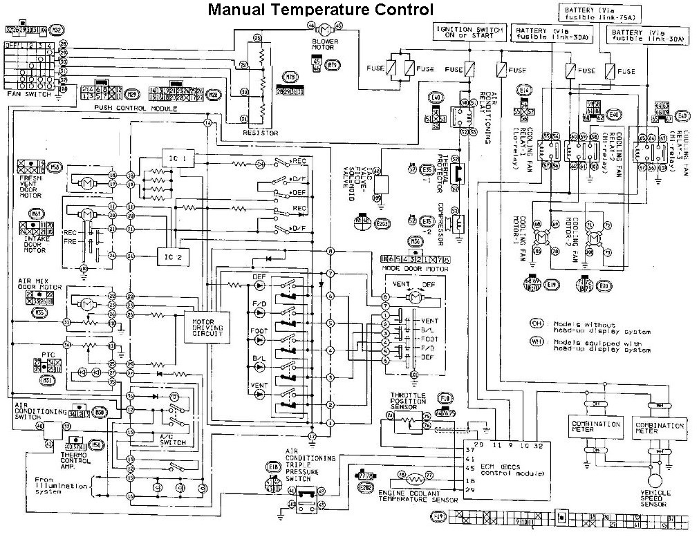
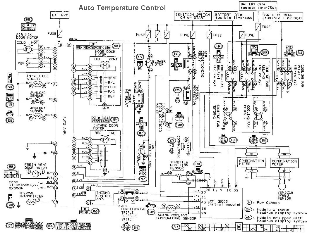
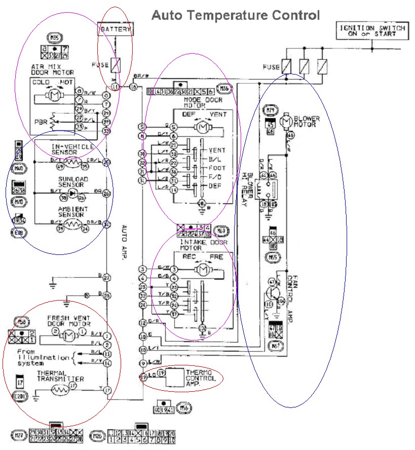
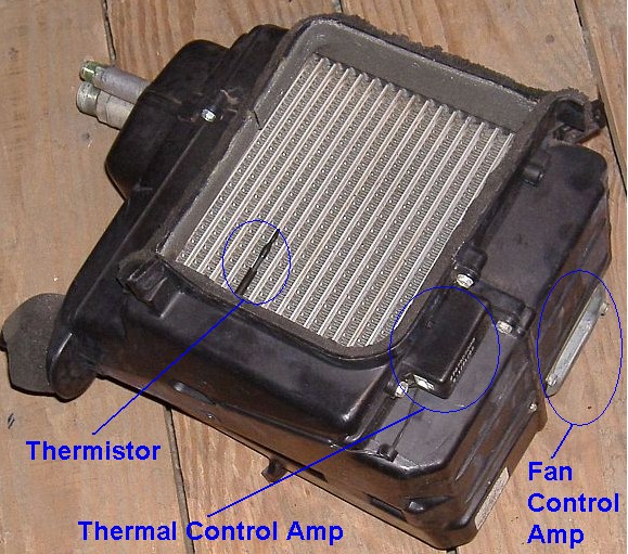
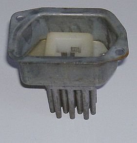
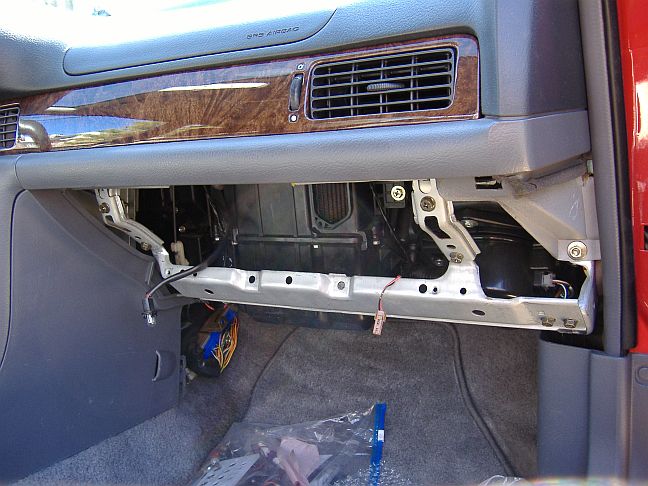
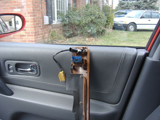
With this post I hope to begin a process that will build over time and show some of the steps taken to produce a fully functional manual temperature control to automatic digital climate control conversion. Anyone that will like to follow along or participate in other ways are fully welcome.

This project is dedicated to all those members that take pride in keeping alive the Altima and sharing their knowledge.

Enjoy,

jserrano
 
See less See more
#3 · (Edited)
Ok, let’s see, where do we begin with this project? Perhaps with an introduction and scope of the project.

Introduction

Nissan, like many other automakers, have taken advantage of advancement in technology and engineering to bring convenience and comfort to its consumers. One area in the auto industry that has seen its share of improvement is the climate control system, i.e. temperature control. Nissan has offered for quite some time a standard or upgrade option, depending on the car model and trim, for in-vehicle temperature control.

There are two types of temperature control, manual and automatic. The manual temperature control (MTC) is the type where you are in full control of the system. The feedback to the system is controlled by a person making changes to the temperature setting.

The automatic temperature control (ATC) is the type where you set a temperature setting and the system automatically senses the local environment to control the system. The feedback to the system comes from a number of sensors that the ATC uses to maintain control over the temperature setting. Remember, we are talking about temperature control.

So, which is a better system? That is really a personal preference question. Both systems controls in-vehicle air volume (blower), air temperature control (slider or setpoint), and air distribution (air mix and discharge) quite well.


Scope

The scope of this project has to be defined. We don’t want to set expectations too high or unattainable.

Who is this project geared for?

In it’s most basic form, if you have a manual temperature control system that looks similar (or somewhat similar) to this,


…then you are in.


Some trim line of the ’93-’97 Altimas offered ATC. Count yourself in again.

The ’98-’01 Altimas didn’t seem to have an ATC option. But you might be able to retrofit one. So you can cautiously count yourself in.

The ’02 – newer Altimas. You guys shouldn’t be in these forums ;). Sorry, you guys have a totally different and better system that is like a mini–multiplexed local area network (LAN) type of system. You can count yourself out.


What is the project’s goal?

To convert you over to an Automatic Temperature Control (ATC) system similar to this,


We would also like to,

• Keep the most wiring and hardware that is already in place.
• If possible, shoot for a dual-system where you can swap in a MTC or ATC with minimal rewiring.
• And lastly, enjoy and learn something from this project.
 
#4 ·
This sounds interesting. At the same time can the ATC be swaped with the position of a DIN radio? I've got an aftermarket Pioneer CD/MP3 radio.
I would love to have the radio closer to eye level. That would allow adjustments to the radio without looking down to take your eye off the road. I seem to remeber someone doing that mod.

An ATC would allow set it and forget it simplicity like I've got in my 3rd gen.

I'm going to keep an eye on this thread :)
 
#5 · (Edited)
System Overview


Let’s begin our discussion of the climate control system from a high-level view. The above illustration is the block diagram layout for this system. Keep in mind that this is from a design perspective that shows the sub-parts of the overall system.

Note: I’ve taken the liberty to make some minor changes to the original drawing so that I can depict the differences between MTC and ATC.

The blocks that are colored in are the actual differences in the ATC. Everything else shown in white color are common to both the MTC and ATC systems.


Control Unit

The control unit is the actual controller in the dash which a person operates to control different functions for heating and cooling. On the MTC it is referred to as the push control module and it is an analog system. On the ATC it is called an auto amplifier and is a digital system with built-in self diagnostics.

In the block diagram, inputs to the control unit are shown with arrows pointing to it. Outputs from the control unit are shown with arrows pointing away from it. This is the main unit that we will be replacing and rewiring. Refer to the pictures in post #3 for reference of each of the control units.


Potentio Temperature Control (PTC)

The PTC is the control where you change the COLD->HOT settings on the control unit. For the MTC it is the slider control
and for the ATC it is setpoint control
. The PTC are different on both systems and it is built into the control unit. It will not be modified.


Ambient Sensor

The ambient sensor detects outside temperature by way of a thermal resistor (thermistor) located in the lower front of the radiator. As outdoor temperature rises the resistance decreases. And as outdoor temperature falls the resistance increases. This relationship between temperature and resistance is known as negative temperature coefficient (NTC).


In-Vehicle Sensor

The in-vehicle sensor detects internal cabin temperature by way of a thermal resistor (thermistor) located behind the center dash piece. A vacuum hose is connected between the in-vehicle sensor and the aspirator. This allows internal cabin air to pass through the sensor to detect temperature. This sensor has the exact electrical specifications as the ambient sensor.


Aspirator

The aspirator is attached to the frontside of the heater core unit. As air is discharged from the heater unit it leaves behind a vacuum within the aspirator. A hose runs from the aspirator to the in-vehicle sensor to draw in cabin air for temperature sensing.


Sunload Sensor

The sunload sensor detect the level of sunshine entering the inside cabin by means of a photodiode. The signal is used to balance the temperature control setting.


Thermal Transmitter

The thermal transmitter detects the coolant temperature and controls fan blower speeds based on “hot soak” or “cold soak”. The idea is to delay sudden hot and cold air blasts to the occupants. This sensor is the exact same one used for the temperature gauge. On my car, it is the bottom sensor pointed to in the following picture,


Fan Control

In the MTC, the intake blower fan speed is controlled by the operator changing the fan switch position. That in turn causes a different resistor value to feed the negative side of the blower motor.

In the ATC, when the system is set to AUTO mode, the intake blower fan speed is automatically controlled by the Fan Control Amplifier located on the cooling unit. The final fan speed is actually based on the feedback obtained from the various sensors and the PTC settings. The AUTO mode can be overriden by the manual fan speed switches on the control unit.


...I'll stop here for the moment and will continue later....

Note: Some of these photos are subject to change on this or other posts as they get expanded and edited. Anyone with better pictures, please send them to me. Thanks. js
 
#7 · (Edited)
System Overview (continued)


Let us continue on with the discussion of the climate control system block diagram. This time we will discuss the common output control signals. We’ll also need to pull in another picture for illustration purposes.

Component Layout Diagram:


Refer to the component layout diagram for actual location of components.


Intake Unit

The intake unit is composed of the blower motor, intake air door motor, some levers for the door flaps, and the blower motor resistor pack for the MTC.

Intake Door Motor

The door flaps on the intake unit is controlled by the intake door motor. 100% of fresh air from the outside or 100% of recirculated air from the inside passes through the intake unit based on the RECIRC button. In the ATC system there is also an additional setting for passing 20% of fresh air. The control unit also receives a feedback from a set of built-in switches in the intake door motor that tells it where the intake door motor is sitting at.


Cooling Unit

The cooling unit is composed of the AC evaporator core, expansion valve, and thermal control amplifier in both MTC and ATC systems.

Thermo Control Amplifier

Ambient outside or inside air coming from the intake unit goes through the cooling unit. When the DEFROST or AC switch is turned ON in the control unit it will enable the thermo control amplifier. The thermo control amp then begins to sense the evaporator’s temperature via a temperature sensing probe that is located in front of the evaporator core. The thermo control amp will then inform the ECU whether to cycle the compressor magnetic A/C relay ON or OFF.

Fan Control

The MTC system contains a blower motor resistor pack on the intake unit that is switched by way of the fan control switch on the control unit.

But for the ATC system, the cooling unit contains a blower HI relay for high-speed fan control and a fan control amplifier for low-speed or additional fan speed control. The fan speed changes automatically if the control unit is in AUTO mode but this can be overriden manually by the operator for total fan speed control.


Heater Unit

The heater unit is actually much more elaborate then what most people assume. It contains more than just the heater core which most people know about. The best way to describe it is to break down each component one by one.

Air Mix Door Motor

Air that comes in from the cooling unit, whether cooled down or not, is mixed with the heater core. The amount of air mixture is based on a door flap. That door flap is driven by the air mix door motor which also has a cable wire running to the inlet water valve on the engine firewall. This valve controls the amount of heated coolant flowing inside the heater core. The air mix door motor also has a built-in feedback system to the control unit that is called a Potentio Balance Resistor (PBR). That is how the control unit knows the position of the door flap. Finally, the air mix door motor setting is electronically controlled by the PTC on the control unit.

Mode Door Motor

If you look at the component layout diagram above you will notice three levels of duct work for air distribution; window defrost comes from the upper section, face ventilation comes from the center section, and foot ventilation comes from the lower section. The mode door motor controls where the system of ventilation door flaps are in relations to the mode setting on the control unit. The control unit also receives a feedback from a set of built-in switches in the mode door motor that tells it where the mode door motor is sitting at.

Fresh Vent Door Motor

This motor turns on additional ventilation from the center section when the unit is in face or bilevel RECIRC mode, the PTC is set to cold, and the AC is running.

Aspirator

The aspirator is mounted on the heater unit. Check the previous posting for its functional description.

Heater Core

The heater core circulates coolant heat via the inlet and outlet hoses on the engine firewall. How much heat flows through it is dependant on the PTC hot settings.


That completes the system overview section of this project. In the upcoming section we will drill down further to take a look at the schematic and wiring diagrams.

Hasta luego.
 
#8 · (Edited)
Circuit Overview

We will now begin to drill down further to another level so we can differentiate between the temperature control systems from a circuit perspective. This will allow us to start taking apart the two systems to get a better view of what is in stake.

First off, we will pull in both MTC and ATC circuits.


I’ve uploaded the pdf versions of them if you would like to have a cleaner diagram. They are at,

http://www.stac-consulting.com/serrano.j/altima/mtc_cir.pdf
http://www.stac-consulting.com/serrano.j/altima/atc_cir.pdf

We will be using the ATC circuit diagram to mark up and denote the changes that will have to be made. But before we begin let us remove the right half of the diagram because it is exactly the same as the MTC and we will not be making any changes to that side anyway.


Now let us use some coloring to show the different parts of the circuit and what we have to deal with.


Red

First off, those items in red can be wired in with simply tapping wires that are already in place.

• Thermo Control Amp – we can tap the original signal from the MTC side.
• Thermal Transmitter – we can tap the signal from the temperature gauge.
• Fresh vent motor – we can tap the signal from the pre-existing MTC side.
• Illumination - we can tap the signal from the pre-existing MTC side.
• Power – we will have to see where to get this unswitched power source from. But there are choices available.


Magenta

From our initial assessment, those items in magenta will most likely stay in place. They are basically the motors. The wiring will have to be reworked somehow because there are some differences particularly with the feedback to the control unit from those motors.

• Air Mix Door Motor – the main issue is with the PBR. The ATC system uses +5VDC while the MTC use +12VDC.
• Mode Door Motor – the feedback switches are wired differently on both systems.
• Intake Door Motor – the ATC has two additional wires ??? We will have to come up with something here.

Update 3/15/2006: Confirmed that the motors will not need to be replaced after all!!! Also, the intake door motor does indeed have pinouts for two additional wires!!!!!!


Blue

Those items in blue will have to be purchased and added in.

• In-vehicle sensor (Part #: 27720-0E000 - $20.31)
• Sunload sensor (Part #: 27721-0E000 - $27.29)
• Ambient sensor (Part #: 27722-0E000 - $27.71 & mounting bracket 27715-0E000 - $5.23)
• Blower HI relay (Part #: 25230-79971 $12.10 w/ mounting bracket 25235-43L00 $1.64)
• Fan Control Amp (Part #: 27761-85E01 $57.25 w/ mounting bracket 27152-0E000 $6.20)
• Aspirator (Part #: 27726-0P000 - $5.00 & hose 27727-1E400 - $3.41) – not shown in the diagram because it is not an electrical component.


There you have it. It seems like, with the exception of those items that will need to be added in, a lot has to do with simply rewiring some stuff around. But the full truth will actually come once the work has begun.
 
#11 · (Edited)
Main Harness Wiring

I decided to do some work on this project over the weekend. So I pull the main harness down from the attic in addition to a few of the other stuff I had purchased about two years ago. This used main harness costed me about $200.00. It is not so much the wiring itself that is highly important. You can buy wiring just about anywhere. But those plugs and connectors that you don't already have in your MTC system will be very important to get in order to finish off this project nicely.


I then pulled apart the ATC wiring from the main harness and kept most components attached. Untangling the wiring was somewhat of a challenge. But I want to do a clean job and keep from doing too much soldering 'down the road'. I removed the blue HI blower relay from the wiring so that it can be installed on the cooling unit.


I pulled the fan control amplifier from the spare cooling unit.


Fan Control Amplifier
Part Number: 27761-85E01 $57.25 w/ mounting bracket 27152-0E000 $6.20


HI Blower Relay
Part Number: 25230-79971 $12.10 w/ mounting bracket 25235-43L00 $1.64


Cooling Unit Components Installation

You need to removed the glove box to get access to the cooling unit. The place to install the fan control amplifier is actually blocked off on the MTC system. You need to removed the cutout for the fan control amplifier. I used a thin flat blade screwdriver and "chiseled" along the outside cutout edges to knock out the soft plastic piece. Then I cleaned up any rough edges with a razor blade. I'm sure a utility knife would also had worked for knocking out and cleaning up the edges too.


The HI blower relay needs a bracket in order to mount it to the left side of the cooling unit. Move the expansion valve lines softly aside so it does not come in contact with the fan control amp fins. Do not kink or seriously bend the lines since this can affect proper AC operations. Use 8mm hex screws for mounting all components.


That completes the installation of two of the components that needs to be added in. I need to order or locate the other components. In the next section I will tighty up the ATC wiring with black tape and then route it to their appropriate destinations.

I will also start to get the power and ground established to the control unit. Why?? So that I can rely on the built-in self-diagnostic system of the control unit to test the different sections as they are being wired in and attached.

Until next time...
 
#13 · (Edited)
ATC is installed and working!!!

Managed to spend some more time over this weekend and I am happy to announce that everything went better then expected.

I strongly recommend that you use electrical tape for organizing and protecting the wiring. Otherwise you will end up with spaghetti wiring that will drive you nuts. Also, labeling the end connectors is a good idea. I'll have to do that on mine.


Connected the in-vehicle sensor. I still need to buy the aspirator and the in-vehice/aspirator hose.


Before you do any electrical work, make sure you disconnect a terminal from the battery post.

TECH TIP: ONLY for those folks with stock type of battery connections.

There is actually a way to disconnect battery power without disconnecting a post terminal. The positive post has a battery TERMINAK piece with two white/red plugs coming off the red plastic piece. Simply unplug those two connectors and you will have no power anywhere in the car. The only live connection is the starter which has it's own separate power feed.

Opened the dash up and routed the wiring. Since my ATC wiring already had all the electrical connectors, I just attached all the plugs to their respective components. The control unit needs constant power on pin 11. I got that from the clock's red wire which is fed by fuse 20 (10A). The control unit also needs ignition switched power on the green/red wire for pin 12. There is a feed on fuse 26 (10A) that goes to the cruise control switch. So I soldered a green/red wire to the green/red wire of the cruise control switch and ran it up to the ATC control unit and the blower relay. Finally, grouped the black wires together and tied them to one of the nuts which is grounded and on the passenger side. I will later redo the ground connection and crimp the wires together on a connector.


Made a quick test before installation,


Made a road test,


(I will come back to clean this writeup. I just needed to show some proof that it works.)

Even though everything works right this project is not finalized. I still need to buy some sensors for the AUTO functions and make a few more electrical connections (thermal transmitter, sunload, etc.) It does work 100% in manual mode. The self-diagnostics shows a problem with code 21 and 25 which are the missing sunload and ambient sensors. Heating, cooling, blower, actuators.. everything else is fine.

Stay tune for further update on this post and others since this project is only about 90% completed.
 
#16 ·
Thanks for the comments guys.

I've read and heard of others trying to do this on the Altima but ran aground for one reason or another. The fact that the intake unit, cooling unit, heating unit, or actuators didn't have to be replaced is what made this project possible. Otherwise, it would probably have been too costly to try and do.

If anyone would like to contribute the sunload sensor, aspirator & hose, or ambient sensor please send me a PM.

I hope this thread will serve useful information for others. Just let me know of anything else y'all will like me to include.
 
#17 · (Edited)
Troubleshooting No AC Auto/Defrost functions

I need to explain something that I just noticed recently with this project. It concerns the AC compressor function.

As previously stated before, I used the self-diagnostic function of the Auto Amp to test the functionality of the system. The only thing that indicated a problem were the sunload and ambient sensors. The self-diagnostic test codes 41 through 46 checks the different ventilation in HOT and COLD. The COLD test kicked ON the AC so I incorrectly assumed that this meant everything was working properly. But during the past week the AC system never came ON with the Auto Amp in AUTO or DEF mode.

I grounded the yellow wire of the Thermo Control Amp and the AC compressor kicked ON. Good, that meant either a Thermo Control Amp or Auto Amp issue. I was sure it had something to do with the Auto Amp so I checked for continuity from the light green wire of the Thermo Control Amp all the way back to the Auto Amp and it was good. This meant the Auto Amp was not controlling the Thermo Control Amp. Something told me the ambient sensor wiring that was hanging loose with no sensor attached had something to do with this. Placed the Auto Amp in self-diagnostic mode 5 which tells you what temperature the in-vehicle and "ambient sensor" were sensing. In-vehicle was at 79°F and the "ambient sensor" was at 22°F. That is it!. The Auto Amp thinks it is too cold outside to operate the AC in Auto or Defrost mode. This feature built into the Auto Amp is called "low temperature protection control".

So I checked the specs on the sensor and it said a resistance of about 2000 ohms is similar to the ambient sensor sensing about 86°F outside temperature. Jumped a 2000 ohms resistor in between the orange/black and black/yellow wires of the ambient sensor and the AC compressor came to life. So there you have it. You need to have the ambient sensor working in order for the AC compressor to kick in. I'll leave the 2000 ohms resistor soldered in until I order the parts. At least the AC will be functioning properly for now. I am almost certain that a disconnected in-vehicle sensor would also had stopped the AC from functioning correctly but I didn't get a chance to test it.

In summary, if you have no AC function from the Auto Amp then check for a missing or disconnected in-vehicle or ambient sensor.
 
#18 ·
Altima A/C problem

Hi All great site you have here,
I have a Altima 1997 that the A/C clutch will not engauge some times.
If I remove the A/C relay and apply 12 volts to pin 52 the motor idles up and the compressor clutch locks, remove the jumper and put the relay back in and high idle but no clutch. Now this does not happen all the time. Any ideas?? Some voltage draw some where?? How much voltage does it take to pull the A/C clutch in?? I will try and attach a print of where I attach the jumper. See arrow on pic
Thanks Russ
 
#20 ·
good shit man. like said earlier, i wish i had your level of ambition as well. i seem to only do complicated things when theres an absolute need for them.
one question though - you installed this thing and it looks like it was a total pain in the ass. my question - why the stock stereo? too complicated?
:D
 
#21 ·
Thanks for the comments guys. And if anyone is still wondering, this project is still incomplete. I do have all the remaining parts, just haven't gotten a break to get this finalized, too many dynamics in my life... But I will update this thread for everyone over time as this project is still ongoing.

Russ G: All the clutch needs is 12V to operate and the alternator or battery are capable of delivery it. The AC relay needs at least 12V on pin 50 and 51 and the ECU will provide ground on pin 53. In order for the ECU to provide ground to the AC relay it needs to be told to do this by the Thermal Control Amp. The Thermal Control Amp has a thermistor sensor sensing the temperature off the evaporator inside the cooling unit. That leads to me to believe that one of the following thiings could be an issue; fan blower not spinning up to speed, low AC freon, bad expansion valve inside cooling unit, clogged evaporator fins, bad thermistor/thermal control amp, and finally bad triple pressure switch. Check this entire thread to familiarize yourself with the components I am talking about. And good luck.

asleepaltima: I did replace the radio with a Kenwood KDC-MP4028 CD/MP3/WMA receiver since nobody cared to steal my stock one. Maybe someday I will get into doing a complete overhaul of the stereo components but for now it'll have to wait.

See you guys around...
 
#23 ·
McgJosh said:
Wow, you have done your research. My only question is why? Not trying to be mean, I am just wondering if it is worth the $200+ and all the time. My ac is almost always on either full cold or full hot with the fan at either 1 or 2. I dont really mess with it.

Great project nonetheless. :bigok:
I would say that "The Challenge" is the driving force. But frankly, pricewise, almost anything done and spent on this car is not worth the value. But many of us just do these types of projects for the enjoyment and to add to the learning matter.
 
#26 ·
jserrano said:
I would say that "The Challenge" is the driving force. But frankly, pricewise, almost anything done and spent on this car is not worth the value. But many of us just do these types of projects for the enjoyment and to add to the learning matter.
if it wasnt for this reason right here - quite a few of us wouldnt even own an altima.
 
This is an older thread, you may not receive a response, and could be reviving an old thread. Please consider creating a new thread.
Top