

This thread came about because of a request from WarMachine for a way to manually control the cooling fans. Here is one way to go about this,
1. First find the cooling fan schematics.
![Image]()
2. Locate the ECU pinout for the cooling fan relay HI control. In this case, I am using a '95 ECU pinout that shows pin 13 for the cooling fan relay HI control.
Note: If you prefer manual control for only low fan speed operations then use ECU pin 14 instead for cooling fan relay LO control.
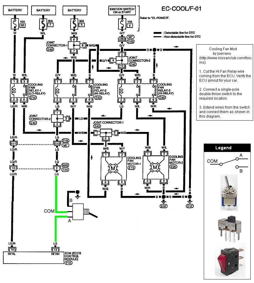
3. Clip the light green wire (pin 13) and connect a single-pole, double-throw (SPDT) switch wired as shown in the schematics below.
![Image]()
Additional notes,
- The cooling fans will run continuously unless it is switched to ECU control.
- Use any SPDT switch such as the toggle, slider, or rocker types.
- The center terminal is normally the COM connection.
- Extend wires from the switch location to the electrical connections.
- Ground to chassis.
Adding a separate temperature gauge that has temperature markings on it will allow you to see and control the temperature setting manually. Keep in mind that the coolant temperature is an ECU fuel injection variable known as temperature enrichment and that this has an effect on the fuel injection time. Running a cooler temperature causes fuel enrichment. Through experiments you should be able to fix an optimal temperature setting which will make the engine perform better.
Good luck with this mod and share your stories with us.
EDIT: 6/20/2008
---------------------------------------
Cooling Fans Relay ECU Pinouts
---------------------------------------
'93-'94
------------
HI - pin 10
LO - pin 9
'95-'01
------------
HI - pin 13
LO - pin 14
1. First find the cooling fan schematics.
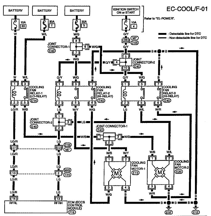
2. Locate the ECU pinout for the cooling fan relay HI control. In this case, I am using a '95 ECU pinout that shows pin 13 for the cooling fan relay HI control.
Note: If you prefer manual control for only low fan speed operations then use ECU pin 14 instead for cooling fan relay LO control.
3. Clip the light green wire (pin 13) and connect a single-pole, double-throw (SPDT) switch wired as shown in the schematics below.
Additional notes,
- The cooling fans will run continuously unless it is switched to ECU control.
- Use any SPDT switch such as the toggle, slider, or rocker types.
- The center terminal is normally the COM connection.
- Extend wires from the switch location to the electrical connections.
- Ground to chassis.
Adding a separate temperature gauge that has temperature markings on it will allow you to see and control the temperature setting manually. Keep in mind that the coolant temperature is an ECU fuel injection variable known as temperature enrichment and that this has an effect on the fuel injection time. Running a cooler temperature causes fuel enrichment. Through experiments you should be able to fix an optimal temperature setting which will make the engine perform better.
Good luck with this mod and share your stories with us.
EDIT: 6/20/2008
---------------------------------------
Cooling Fans Relay ECU Pinouts
---------------------------------------
'93-'94
------------
HI - pin 10
LO - pin 9
'95-'01
------------
HI - pin 13
LO - pin 14


